WhatIsInductionHeating

Induction Heating is based on the supply of energy by means of electromagnetic induction.

A coil, suitably dimensioned, placed close to the metal parts to be heated, conducting high or medium frequency alternated current, induces on the work piece currents (eddy currents) whose intensity can be controlled and modulated.

The heating occurs without physical contact, it involves only the metal parts to be treated and it is characterized by a high efficiency transfer without loss of heat.

The depth of penetration of the generated currents is directly correlated to the working frequency of the generator used; higher it is, much more the induced currents concentrate on the surface. In this case, the heating homogeneity on a relevant mass, can be obtained due to the principle of thermal conduction which allows the heating to be transferred in depth

Benefit and Advantages of Induction Heating

Induction Heating is widely applied on industrial heating applications and it allows to get:

  • Reduced Heating Time
  • Localized Heating
  • Efficient Energy Consumption
  • Heating Process Controllable and Repeatable
  • Improved Product Quality
  • Safety for User
  • Improving of the working condition

How does induction Heating works?

The phenomenon of the electromagnetic induction heating is based on three physical principles, here below explained:

  1. Transfer of energy from the inductor to the piece to be heated, by means of Electromagnetic Fields.
  2. Transformation of the electric energy into heat due to Joule effect. (P=I2R)
  3. Transmission of the heat inside the mass by means of Thermal Conduction.

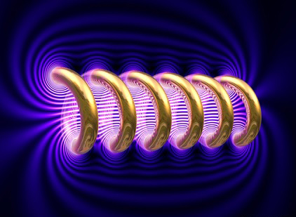
The electro-magnetic field is generated by the current flowing on the coil.
If the coil has got a solenoid shape, the intensity of the electro-magnetic field is proportional to the number of loops of the coil as well.
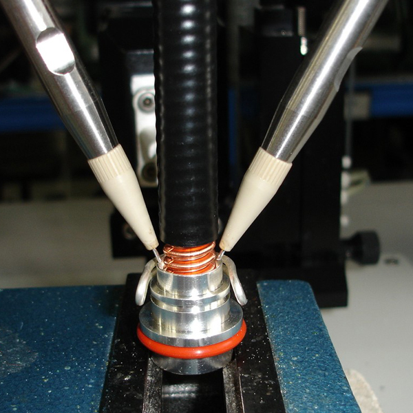
A workpiece that is placed inside or nearby the heating coil, are induced parasitic current, also called eddy currents.

According to the Laplace Law, the intensity of the magnetic field is reverse proportional to the square of the distance from the coil.
According to Faraday-Lenz’s Law, the induced current generated on the workpiece is proportional to the rate of change of the magnet flux (Frequency).
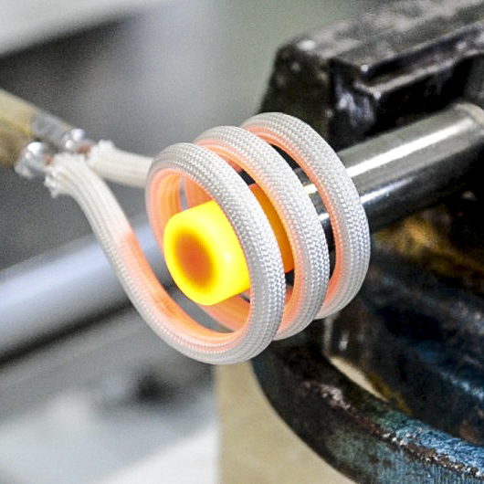
Eddy currents are currents induced in conductors, opposing the change in flux that generated them. They are caused when a conductor is exposed to a changing magnetic field.
These circulating eddy current create induced magnetic fields that oppose the change of the original magnetic field due to Lenz’ laws, causing repulsive or drag forces between the conductor and the coil.
The stronger the applied magnetic field, or the greater the electrical conductivity of the conductor, or the faster the field that the conductor is exposed to changes, then the greater the currents that are developed.

The energy induced on the workpiece to be heated is therefore a function of:

  1. Current intensity on the coil
  2. Operating frequency
  3. Coil shape and distance to the workpiece
  4. Workpiece magnetic permeability and resistivity (influenced by target temperature and Curie Temperature for magnetic items)

Skin Effect

Skin effect is the tendency of an alternating electric current (AC) to distribute itself within a conductor with the current density being largest near the surface of the conductor, decreasing at greater depths.

The skin effect is due to opposing eddy currents induced by the changing magnetic field resulting from the alternating current. Therefore, the higher the working frequency, the more on the external surface of the workpiece will be focused the induction heating.

Induction Heating Coil

It is used to transfer energy to the piece. The Coil design is one of the most important elements of the system as is a science in itself.The coil is designed to:

  • focus the heating only where necessary
  • maximize the heating efficiency
  • allows the integration on the production machine

Structure and History of Inductive Heating Generators

An induction heater typically consist of three elements

  • Power Unit (inverter/generator): This part of the system is used to take the mains frequency and increase it to anywhere between 20÷900 kHz. The typical output power of a unit is from 2 to 500 kW.
  • Work Head: This contains a combination of capacitors and transformers and it is used to match the power unit to the work coil
  • Work Coil (inductor): Is used to transfer energy to the piece. Coil design is one of the most important elements of the system as is a science in itself

Power Unit (Generator)
Work Head(network matching) with Work Coil (inductor)

Classic Structure - Valve Oscillator Generator (1970-1990)

The multi-electrode thermo-ionic vacuum triode (valve) was the heart of the self-oscillator circuit that was responsible for creating the elevated frequency electrical current, that flows on the coil.

Problems:
  • Output power instability: The output power is affected by power supply voltage fluctuation, and the generator is not able to follow the set power in case of load variation (i.e. heating over Curie Point)
  • Difficult power regulation
  • Low efficiency (nearly 60 %)
  • Valve lifetime
  • Very High anodic voltage (Danger for operator safety)
  • Large Overall Dimensions

Conventional Structure (1990 – Today) - Solid State Transistor Generators

Nowadays the use of MOSFET or IGBT transistors has replaced the use vacuum valves, and is become the heart of all conventional inductive heating generators in the market.

Main Features:

  • Overall dimensions smaller then valve generators
  • Higher efficiency
  • Higher working frequency range

Problems:

  • High current flow from generator to Heating Head
  • Output power instability in case of mains voltage fluctuation, or load variation
  • The use of the conventional generator is possible in heating process with large admitted tolerances.

CEIA Induction Heating Generators

Main Features and Difference vs. conventional generators

  • Real-Time Micro processor control of the power generation
  • Extremely compact design
  • Coil voltage feedback sensors
  • Resonant Heating Head (low current flow from generator to heating head)
  • Maintains stable output power even as working conditions change (calibration report)
  • Specific Control unit for output power control
  • EMC and CE certified

Accurate Control Loop through feedback of:

  • Coil Voltage
  • Coil Current
  • RF Output Phase
  • Input Current
  • Optical Pyrometer for temperature control (80÷2200 °C) (175÷3990 °F)

Total of 5 feedback parameters to ensure a precise and consistent heating process.

The CEIA inductive heating system allows to a very fast and accurate temperature control. They are suitable for industrial and automatic process , they are installed also on robotic system where is required:

  • Extremely high Repeatability
  • No Tolerance Admitted
Presentazione

Presentazione Aziendale

Da oltre 40 anni CEIA si dedica alla progettazione ed alla realizzazione di apparati per il riscaldamento ad induzione senza contatto di particolari metallici industriali. Generatori ad induzione ad alta e media frequenza, centrali di controllo, sensori ottici per la misura della temperatura e distributori automatici di lega di brasatura in filo, compongono una linea di apparati, denominata Power Cube Family, progettati per le applicazioni industriali di trattamento termico, brasatura ad induzione, riscaldamento localizzato, forgia, stampaggio a caldo, polimerizzazione ad induzione, brasatura alluminio, calettamento/piantaggio a caldo.
L’originalità delle soluzioni tecnologiche adottate ha permesso di realizzare dispositivi caratterizzati da dimensioni d’ingombro molto contenute, rendimenti energetici elevatissimi ed affidabilità garantita nel tempo.
Le elevate prestazioni offerte hanno contribuito alla larga diffusione dei sistemi CEIA nei più importanti settori industriali, incontrando il favore di clienti finali ed integratori.

Presentazione Aziendale

Zona Industriale 54
Viciomaggio - Arezzo
52041
IT